| zorki standard
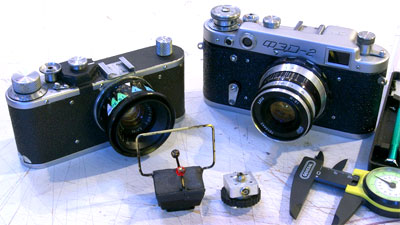
I've been out shooting with the Zorki Standard. I'm *really* liking it. I picked up my broken FED 2 the other day and hadn't realized how much bigger it was compared to the Zorki Standard. The little Zorki is really small and light. I'm also getting used to using the Gordodot wireframe. I'm liking it, too. Even though the Gordodot is working fine, the esthetics do leave a little to be desired. The base is visually to bulky, the wireframe is on at a slight angle, which really doesn't affect anything, but I've been wanting to do something about it. And the black put on by the Sharpie Magic Marker wasn't that magic. It comes off but it let me know that the wireframe wants to be black. I finally found the metal foot that I bought some time ago to replace the plastic foot on my Vivitar 283.
It never made it on the 283 and I've moved up to a Metz C-45 so it is never going to be going on the 283. You can get them on eBay for under $10. Search for Vivitar 283 foot.
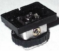
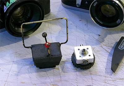
I removed the plastic top. The next step is to drill out the flash bits in the center, drill some holes to insert the wireframe, file the metal down a bit, paint it black and I will have the improved, and lower profile, Gordodot Mark II.
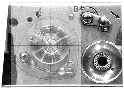
The paper shutter mechanism cover is temporary. I've developed the shape for a permanent shutter mechanism cover. I took a photo of the top of the camera and then printed it out large on a piece of paper. I can convert measurements taken on the print and scale them down. This makes it much easier and a lot more accurate than directly measuring the camera. The width of the camera body is the reference dimension. There is some motion of the cam so I have two pictures superimposed showing the full range of motion. (Digital does come in handy.) Add a little clearance and there is the plan view.
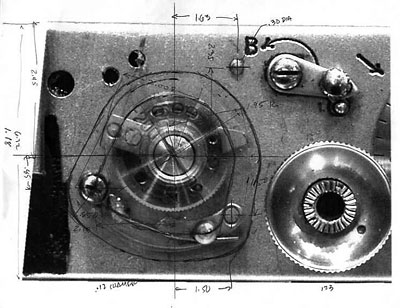
It turns out that most of the dimensions I wrote down weren't needed. (Some are even wrong. I'm not saying which. ) I scaled some points off of the pencil sketch (above) and drew it up on my CAD program. I saved it as a bmp file and brought it back into Photoshop to check clearances. It needed a little tweaking.
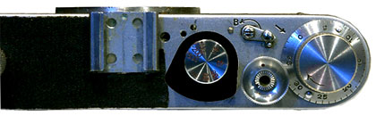
Then I put a filled in version on the photograph to get a better idea what it would look like. It's going to be small.
Now to find an appropriate piece of wood, print out the drawing, glue it on top of the wood, and start removing wood. When the wood shape is done I will use it as a form to hammer form some soft aluminum into the final shape.
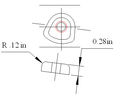
The hole in the wood is for some 1/2 threaded rod to hold on to the little sucker with. The red circle is the clearance hole that will be in the cover. I've been planning on hammer forming aluminum but this could be used as a form for fiberglass, too. Or how about a carbon fiber covering?
|